Orientation control
Mark the mounting face and sensing direction, especially for paired or mirrored brackets.
Bent stainless steel sensor brackets that place a detector at an angle to its mounting surface. Device cutouts, threaded-body clearances and fixing slots are matched to the actual sensor interface.
Laser cutting · Bending · Supporting machining
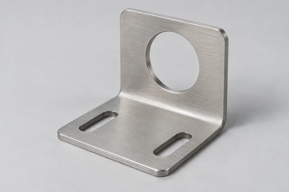
The dimensions below help us review sensor angle brackets. State units and critical tolerances on the original drawing. The illustration explains the type of geometry; it does not define a standard size.
| Device opening | Provide the sensor body and mounting interface dimensions. |
|---|---|
| Sensing orientation | Show the required axis relative to the base. |
| Bend geometry | Give finished leg dimensions, angle and inside radius. |
| Connector space | Define clearance behind the sensor and around its cable. |
| Material & quantity | Give the exact metal grade, standard, temper or condition, quantity per revision and planned repeat orders. |
| Units & tolerances | Use mm or inches consistently. Mark the dimensions that control fit and the inspection datum. |
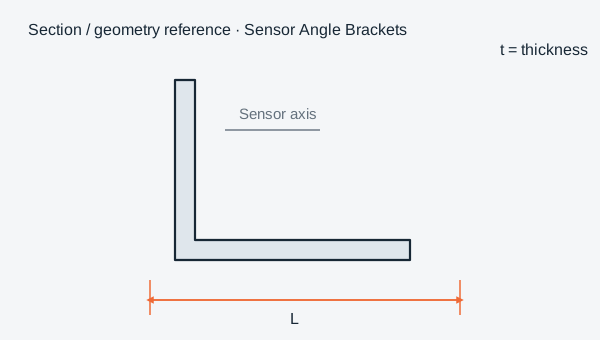
Thickness range, minimum features, tolerances, finish availability and delivery date are reviewed for your actual part. No catalog dimension or blanket machining tolerance is implied.
Finished dimensions and the relationship between cutting, bend direction and the assembly interface.
Mark the mounting face and sensing direction, especially for paired or mirrored brackets.
A short leg with a large sensor opening needs a tooling and forming review before the layout is finalized.
Grade, environment and visible-face requirements are separate specification choices. Include them before quotation so the material and process route can be reviewed together.
Stainless steel options include 304, 304L, 316, 316L, 430 and duplex 2205. Carbon steel, galvanized steel, aluminium, copper and brass can also be discussed for your drawing. State the exact grade and applicable material standard.
Read the grade selection reference for general material context. Availability, product form and suitability are confirmed for the project. Explore all six material families.
Identify a mill finish, brushed appearance or another specified finish; include the visible face, grain direction and any surface-roughness requirement.
Specify edge deburring, protective-film handling and packing if they affect the delivered part. Read the finish terminology guide.
Material options are reviewed against your drawing, grade, thickness and finishing needs. Stainless steel remains our core focus; sourcing and the manufacturing route are confirmed during quotation.
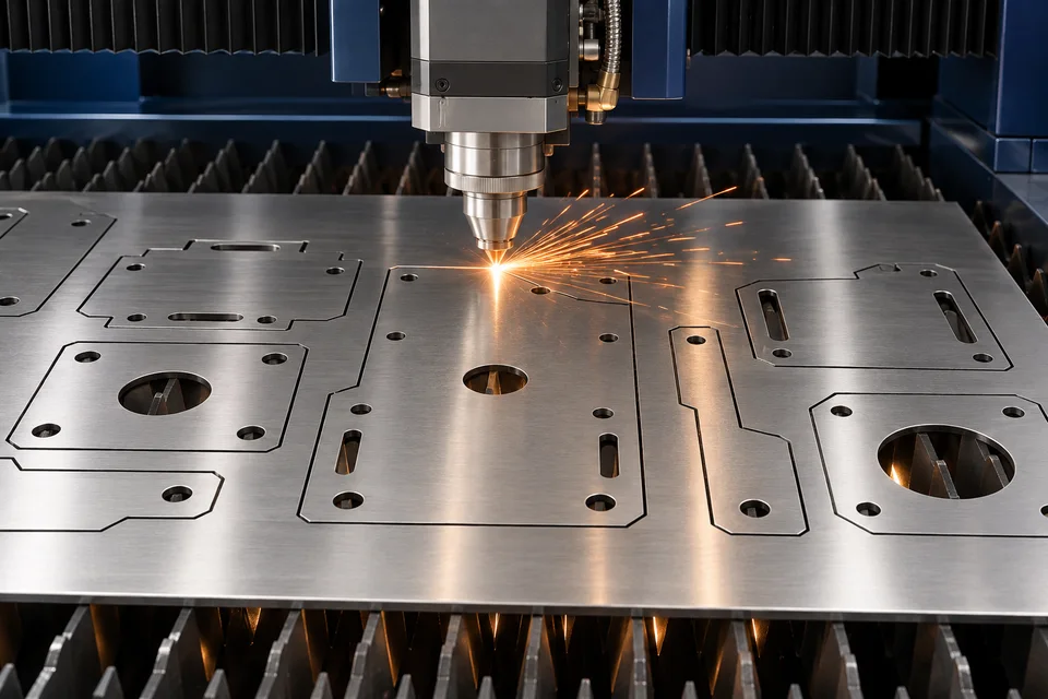
Check the sensor opening, bracket angle and location of the sensing axis relative to the base datum.
Provide the inspection datum, critical dimensions and any requested records with the inquiry. A model preview supports communication; the approved engineering drawing remains the manufacturing reference.
Quality & material requirementsA photo can explain the application, but include the device mounting drawing and desired bracket dimensions for a reliable technical review.
Send your sensor angle brackets drawing, grade, thickness or tube section, quantity, finish and critical dimensions. A clear PDF or image is accepted for review; a DXF supports flat cutting contours.
Include prototype quantity and expected repeat quantity in the inquiry. Batch size, process route and lead time are confirmed after the drawing and specification review.
Send the file and procurement requirements. No customer account is needed.
Upload & Request a QuoteCompare the geometry and drawing requirements.
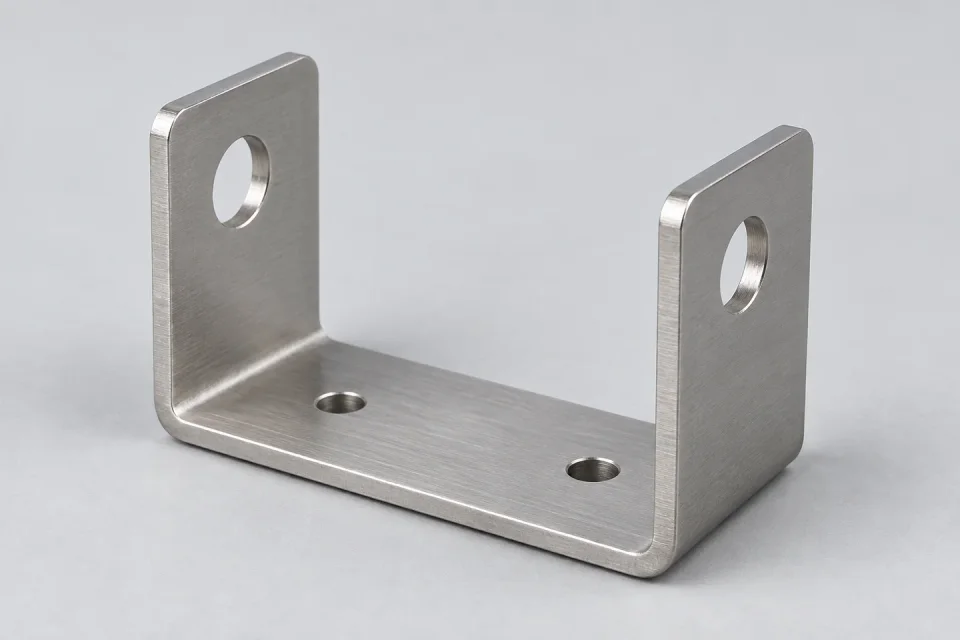
Stainless steel U brackets with two formed sides for capturing or locating a mating component.
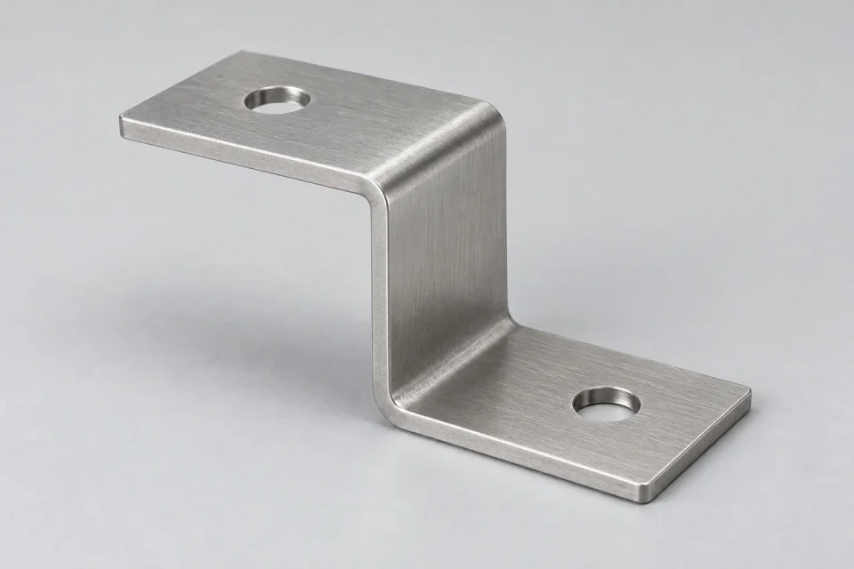
Part details & dimensionsCustom Z-shaped stainless steel brackets for mounting surfaces at different heights.
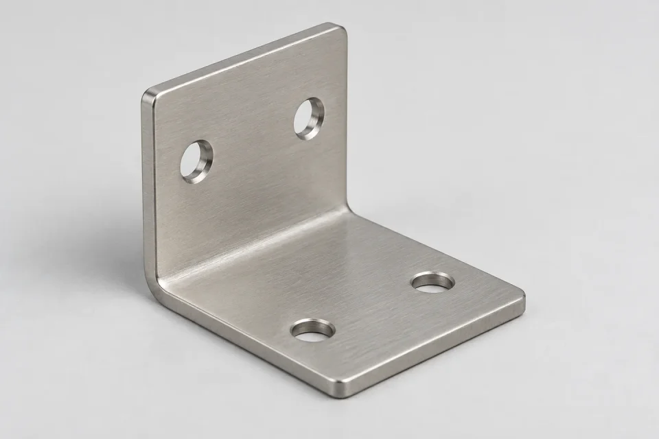
Part details & dimensionsCustom stainless steel L brackets made from a cut blank with a defined bend.
Part details & dimensionsDrawing checklist and custom laser cutting quotation factors.